TDK Front Line
Vol.3 TDK’s LTCC AiP Technology Supports 5G Communications

Fifth-generation (5G) mobile communications system services, the successor to LTE/4G communications, are starting up worldwide. In 5G communications, radio waves in the millimeter wave band are used to achieve ultrafast large-capacity servi ces, multiple concurrent connections, and ultra-low latency. Large numbers of super multi-element antennas installed in small base stations play an extremely important role. Making full use of low temperature co-fired ceramic (LTCC) technology accumulated through manufacture of high-frequency components and modules, TDK is developing an LTCC antenna-in-package (AiP) device that integrates an antenna array as a key device for super multi-element antennas with band-pass filters (BPFs). Use of a new LTCC material with a low dielectric constant and low loss ensures the advanced characteristics necessary for 5G communications and enables flexible 5G communications system design with superior mass productivity, environmental resistance, and heat dissipation.
- Three key characteristics of 5G communications: ultrafast large- capacity services, multiple concurrent connections, and ultra-low latency
- Super multi-element antennas and beam forming are key technologies for 5G communications
- TDK’s LTCC technology utilized in super multi-element antennas
- LTCC AiP device that integrates antenna element and BPF
Three key characteristics of 3G communications: ultrafast large- capacity services, multiple concurrent connections, and ultra-low latency
Featuring the three key characteristics of ultrafast large-capacity services, multiple concurrent connections, and ultra-low latency, 5G has been attracting much global interest as communications infrastructure for an IoT/IoE society where everything is interconnected via the internet.
Unlike conventional mobile communications, 5G communications use radio waves in the millimeter wave* band. Communication speeds are more than 10 times faster than those available in 4G, offering large-capacity communications that will enable users to download a high-definition movie in just a few seconds.
*Generally speaking, millimeter wave (EHF wave) refers to radio waves with a wavelength of 1 to 10 mm and a frequency of 30 to 300 GHz. In 5G communications, radio waves in a frequency range of about 24 to 100 GHz, including microwaves (SHF waves) around 24 GHz, are called millimeter waves. In this article, the term “millimeter waves” refers to radio waves in this range. Note that 5G communications use microwaves below 6 GHz as well as the millimeter wave band.
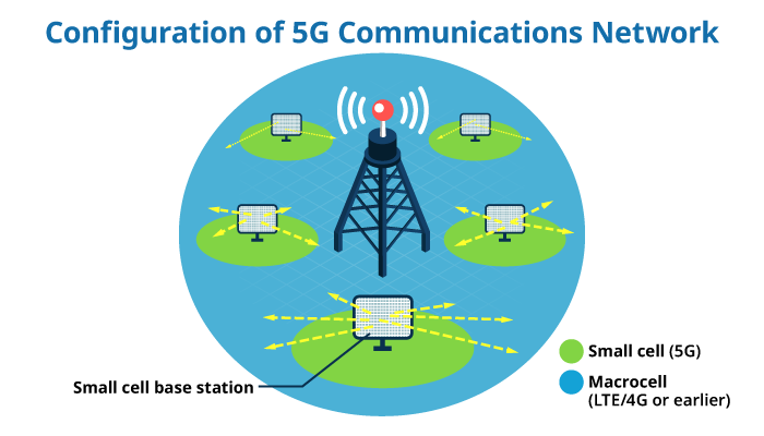
The higher the frequency of a radio wave, the more properties of light it exhibits; that is, it is straighter and travels over a shorter range. Accordingly, in a 5G system using radio waves in the millimeter wave band, the communications area covered by a base station is smaller than in an LTE/4G system. Thus, in 5G communications, as illustrated below, services are offered via an overlay network where a large number of small cells that cover 5G communications are overlaid on a macrocell that covers communications via the existing LTE/4G or earlier systems.
As well as ultrafast large-capacity communications, 5G provides multiple concurrent connections enabling as many as one million devices per square kilometer to be connected to one another using a technology called beam forming, which is described below.
Another major characteristic of 5G is ultra-low latency, meaning that there are effectively no communication delays. This allows vehicles or machines to be operated remotely with no time lag. It is hoped that integration with robotics technology will also make this capability available in such fields as telesurgery.
While 5G enables a variety of applications that have been unavailable with conventional communication systems, a large number of technical challenges must be resolved before implementation and widespread adoption of 5G communications.
Super multi-element antennas and beam forming are key technologies for 5G communications
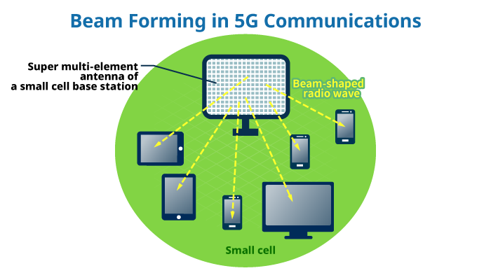
Base station super multi-element antennas and beam forming are key technologies for 5G communications designed to concurrently connect a large number of devices without any latency while overcoming the drawback that milliwave communications have a short range.
Super multi-element antennas, which are multi-antennas composed of a large number of (tens to 100 or more) antenna elements, control the phases of a signal radiated from an antenna element to beam radio waves to a distance and discretely transmit radio waves to each of a large number of devices. This technology is called beam forming.
TDK’s LTCC technology utilized in super multi-element antennas
A planar array antenna, in which a large number of antenna elements are arranged in a matrix shape, has been developed as a super multi-element antenna for 5G base stations. Individual antenna elements of the planar array antenna are installed at a spacing of about half the radio wave in use. For example, the spacing between elements is about 7.5 mm for a radio wave with a frequency of 20 GHz, and a planar array antenna including 16 x 16 = 256 elements occupies an area about 12 cm square. In frequency bands above 20 GHz, more antenna elements can be integrated within the same area.
Note that because BPFs or ICs are connected to an array antenna, downsizing of the entire system greatly depends on the manufacturing method used for the array antenna.
Millimeter waves are prone to shielding by obstacles. To maintain stable communications in streets lined with office buildings or shopping malls, it is necessary to install a large number of small base stations. This requires a manufacturing method that can mass-produce super multi-element antennas as key devices at low cost. LTCC is attracting renewed attention as an ideal manufacturing method for this purpose.
LTCC is a multilayer ceramics substrate construction method developed to manufacture high-frequency components and modules. In principle, a filter such as a BPF is a circuit composed of a combination of an inductor (L) and a capacitor (C). Discrete components such as chip inductors or chip capacitors cannot be used in high frequency ranges. To address this problem, as illustrated in the following schematic view, a metal conductor microscopic wiring path (micro strip line) is formed on a dielectric ceramic sheet, and inductor or capacitor functions are delivered via the conductor pattern to manufacture high-frequency components or modules such as BPFs.
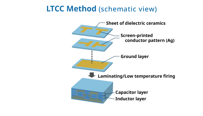
Since the resistance component of a conductor pattern lowers filter characteristics in high frequency ranges, the conductor uses silver (Ag), which has low resistance. Bearing in mind that the melting point of silver is 960°C, firing a silver conductor at the usual firing temperature for ceramics (around 1300°C) causes a conductor pattern to melt and decompose. A substrate material has thus been developed in which a special glass component is mixed with an alumina-based ceramic material so that a silver conductor can be fired at a relatively low temperature (about 900°C) that is below the melting point of silver. The LTCC method uses this low-temperature-fired ceramic substrate to screen-print conductor patterns serving as an inductor section and a capacitor section, laminate the patterns onto each other, and finally perform low-temperature firing on the laminate.
LTCC AiP Device that Integrates Antenna Element and BPF
In the manufacture of high-frequency components and modules using the LTCC method, the capacitor layer and the inductor layer each uses a ceramic sheet of a different material. The former uses a ceramic sheet with a high dielectric constant and the latter a ceramic sheet with a low dielectric constant in order to downsize the components and improve their characteristics. When these sheets are laminated onto one another and co-fired, problems of warpage and peeling arise due to differences in the coefficient of thermal expansion. TDK has pioneered an advanced LTCC method that uses technology for co-firing different materials to solve these problems, and has commercialized and supplied high-frequency filters and front-end modules for mobile communication devices.
TDK has developed an LTCC AiP device for super multi-element antennas used in 5G communication base stations by making full use of its technology for co-firing different materials as well as LTCC technology built up over many years.
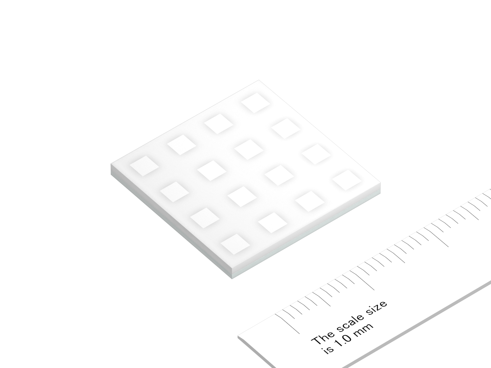
As illustrated in the product image and cross-sectional view below, the LTCC AiP device is a composite device with a structure (AiP) in which a 4 × 4 antenna element is integrated with a BPF using the LTCC method. The ability to integrate the antenna element with the BPF in a single process and manufacture a large-sized substrate for implementing an array antenna are inherent advantages of the LTCC method. TDK can offer a product including only an antenna element or only a BPF to meet specific customer applications.
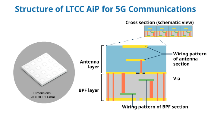
A key characteristic of the LTCC AiP device is the use of a newly-developed LTCC material with a low dielectric constant for the antenna layer and the use of a material with low loss (high Q characteristics) for the BPF layer, thereby attaining a high gain even in the millimeter wave band. The LTCC AiP has excellent environmental resistance and heat dissipation characteristics compared to resin substrate products. Another merit of this device is broad freedom of design. Easily adaptable to a variety of frequency bands including the 26 GHz, 28 GHz, and 39 GHz bands, the LTCC AiP device delivers excellent performance for super multi-element antennas used in the RF transceiver circuits of 5G communication base stations. TDK plans to offer characteristic evaluation/adjustment support services for customers who have incorporated an LTCC AiP device into their sets by using facilities including a millimeter-wave anechoic chamber.
- Three key characteristics of 3G communications: ultrafast large- capacity services, multiple concurrent connections, and ultra-low latency
- Super multi-element antennas and beam forming are key technologies for 5G communications
- TDK’s LTCC technology utilized in super multi-element antennas
- LTCC AiP device that integrates antenna element and BPF